
Oct 30, 2026 | By dadaxSee UTS Developing Team
1. Introduction
In modern industrial ultrasonic testing (UT) systems, as ultrasonic data acquisition equipment evolves toward multi-channel architectures, high sampling rates, Phased Array Ultrasonic Testing (PAUT), and Full Matrix Capture / Total Focusing Method (FMC/TFM), massive radio frequency (RF) data poses severe challenges to system data transmission buses, real-time computation, and data archiving.
When designing and configuring an ultrasonic data acquisition system, engineers must evaluate and balance five core performance metrics:
- Pulse Repetition Frequency (PRF): Determines the pulser excitation capability per unit time and the upper limit of scanning speed.
- Signal-to-Noise Ratio (SNR): Determines the system’s ability to detect and identify small or deep-seated flaws.
- Pulse Width: Determines axial resolution and near-surface resolution (fundamentally an analog property).
- Test Data File Size: Determines hardware storage costs and data I/O bandwidth consumption.
- Testing Speed: A primary throughput metric for automated production lines and on-site industrial inspections.
To strike a balance between high-quality imaging and real-time data transmission/storage, Decimation, Averaging, and Data Compression are widely applied in ultrasonic acquisition systems. This article explores the underlying mechanisms of these three Digital Signal Processing (DSP) techniques and systematically analyzes their profound impacts on the five core metrics and spatial resolution.
2. Core DSP Technologies and Principles
2.1 Decimation (Downsampling)
- Primary Goal: Reduce the effective sampling rate of the signal and decrease the number of sample points per A-scan.
- Working Mechanism: Standard digital decimation consists of two tightly coupled steps:
- Anti-Aliasing Digital Low-Pass Filtering: Filters out high-frequency components above the new Nyquist frequency ($F_{\text{new}}/2$).
- Downsampling: Retains one sample every D sample points (D is the decimation factor): $$y_{\text{dec}}[m] = x[m \cdot D] \quad (\text{fter anti-aliasing filtering})$$
- Aliasing Warning: If downsampling is performed directly without anti-aliasing filtering, frequency components higher than the new Nyquist frequency will “fold” into the lower frequency band (with folded frequency $\vert{}f – k \cdot f_s\vert{}$), causing false low-frequency artifact distortion. Once aliasing occurs, it cannot be reversed digitally.
2.2 Signal Averaging (Ensemble Averaging)
- Primary Goal: Improve signal quality and SNR by reducing random background noise.
- Working Mechanism: Provided that the transducer and workpiece remain physically stationary relative to each other (stable trigger), the system sequentially acquires M frames of A-scan signals at the exact same location and performs point-by-point coherent summation and averaging:
$$y_{\text{avg}}[n] = \frac{1}{M} \sum_{i=1}^{M} x_i[n]$$ - Principles and Performance:
- Noise: Assuming electronic and thermal noises are zero-mean random independent signals, the noise amplitude approaches zero after averaging.
- Signal: Real ultrasonic flaw echoes exhibit phase coherence and are reinforced during coherent summation.
- SNR Improvement: SNR improvement is directly proportional to the square root of the number of averages ($\sqrt{M}$ times improvement; for instance, 16 averages yield a ~12 dB / 4x improvement in SNR).
2.3 Data Compression
- Primary Goal: Reduce the number of bits required to represent the signal, lowering storage and transmission overhead.
- Working Mechanism: Applied to digitized A-scan data streams or full matrix datasets, categorized into two types:
- Lossless Compression: Uses Run-Length Encoding (RLE), Huffman coding, etc., typically achieving a compression ratio around 2:1 with no data distortion upon decompression.
- Lossy Compression: Discards minor high-frequency redundancies or weak background noise (e.g., via wavelet transform quantization), achieving compression ratios of 10:1 or higher at the expense of minor reconstruction errors.
3. Comparison of Effects on Key Ultrasonic Testing Elements
The following table summarizes the specific mechanisms and effects of decimation, averaging, and compression on key engineering parameters in ultrasonic testing:
| DSP Technique | Effect on PRF | Effect on SNR | Effect on Pulse Width | Effect on Data File Size | Effect on Testing Speed | Effect on Spatial / Axial Resolution |
|---|---|---|---|---|---|---|
| Decimation | No direct effect (Applied post-acquisition) | ↑ Slightly improves (Low-pass filter removes HF noise) | ↑ Apparent widening (Sharp HF edges are smoothed; rise time increases) | ↓ Proportionally reduces (Reduces file size to 1/D) | ↑ Potential increase (Eases bus I/O pressure, maintaining high PRF) | ↓ Decreases axial resolution (Proportional to bandwidth reduction) |
| Averaging | ↓ Reduces effective PRF (Effective PRF = Original PRF / M) | ↑ Significantly improves (Improved by $\sqrt{M}$) | No direct change (Cleans up signal representation) | No change (Outputs a single final A-scan) | ↓ Significantly reduces (Scanner must pause at each point for M triggers) | No direct change (Motion jitter may cause slight phase cancellation) |
| Compression | No direct effect | Lossless: No change Lossy: May degrade or artificially inflate | Lossless: No change Lossy: May smooth or widen pulse shape | ↓↓ Dramatically reduces (2:1 to >10:1) | ↑ Significantly increases (Speeds up data transfer and storage) | Lossless: No change Lossy: HF loss reduces resolution |
4. Decimation, Averaging, and Compression in dadaxSee UTS Software
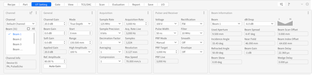
In dadaxSee UTS software, these three core parameters can be configured under the Workbench via Settings > UT Settings > Acquisition (labeled as Decimation Factor, Averaging, and Compression in the user interface). It should be noted that the availability and optional value ranges for these parameters depend on the connected ultrasonic hardware/instrument and inspection type:
- Decimation Factor: The baseline sampling frequency (MHz) divided by the decimation factor determines the actual active sampling frequency. Sampling rate dictates the analog-to-digital conversion speed; higher frequencies correspond to shorter time intervals between data points. The decimation factor is primarily used to lower the sampling rate and directly impacts A-scan resolution. By discarding samples, it reduces data rates, making signals easier to process and store.
- Averaging: Defines the number of A-scans to be averaged per scan point. Averaging proportionally divides the hardware Pulse Repetition Frequency (PRF) value. For example, changing the average value from 1 to 4 reduces the effective PRF from 1 kHz to 250 Hz. The pulser still fires at 1 kHz, but all 4 pulse echoes are averaged to generate a single output signal. This function suppresses random noise and improves SNR; a value of 1 indicates that averaging is disabled.
- Compression: A-scan compression ratio (a value $\ge 1$). Compression is mainly used to lower bitrate and decrease the data size needed to represent the signal. For instance, a compression value of 6 retains the maximum peak value out of every 6 consecutive acquired sample points, ensuring no critical peak values are missed. A compression value of 1 indicates that compression is disabled.
5. Engineering Best Practice Guidelines
In practical industrial applications, adopting differentiated DSP algorithm strategies according to specific inspection requirements helps achieve an optimal balance between inspection speed, signal clarity, and file storage:
Scenario A: High-Speed Automated Screening (e.g., Pipe/Weld In-line Inspection)
- Core Requirement: Maximum inspection throughput; primary focus is rapid detection of major defects.
- Recommended Setup: Maintain maximum hardware PRF + Decimation Factor $D = 2 \sim 4$ + Lossy/High-ratio Compression; Disable Averaging.
- Engineering Benefit: Relieves system bus bandwidth and storage I/O bottlenecks, allowing the scanner to operate at maximum speed.
Scenario B: High-Precision Critical Inspection (e.g., Aerospace & Nuclear Component Re-inspection)
- Core Requirement: Maximum SNR and accurate defect sizing/characterization; zero tolerance for missing small cracks.
- Recommended Setup: Moderate scanning speed + Signal Averaging ($M = 4 \sim 16$) + High sampling rate (Disable Decimation) + Lossless Compression.
- Engineering Benefit: Reveals weak echoes buried under background noise, preserves sharp pulse rise times, and ensures highest axial resolution.
Scenario C: Phased Array FMC/TFM High-Volume Data Acquisition
- Core Requirement: Eliminate Gigabit Ethernet / PCIe transmission bottlenecks and prevent real-time TFM imaging lag.
- Recommended Setup: Moderate Decimation at hardware acquisition + Real-time FPGA hardware-level Lossless/Low-loss Compression.
- Engineering Benefit: Resolves multi-channel raw data explosion at the source, balancing transmission bandwidth with real-time imaging frame rates.
6. Conclusion
Decimation, averaging, and compression in industrial ultrasonic testing are not isolated algorithm options, but rather interconnected levers for balancing system performance. By understanding their mechanisms on PRF, SNR, pulse width, file size, and testing speed—combined with the flexible configurations in dadaxSee UTS—engineers can tailor optimal non-destructive testing solutions under hardware-constrained environments.